What MPS Is
PCIe devices transfer data in packets called Transaction Layer Packets (TLPs). Each TLP has a header and a payload. The maximum size of that payload is the MaxPayloadSize (MPS).
MPS is negotiated between a device and its upstream bridge during link training. The negotiated value is the smaller of what the device supports and what the bridge allows. Every bridge and switch in the path between the device and the root complex has its own MPS capability. The final MPS for any device is set by the narrowest point in the chain.
Common MPS values are 128, 256, and 512 bytes. Some devices support 1024 or even 4096 bytes, but in practice 256 or 512 is typical for NVMe controllers and network cards. GPUs often support 256 bytes.
Why It Matters
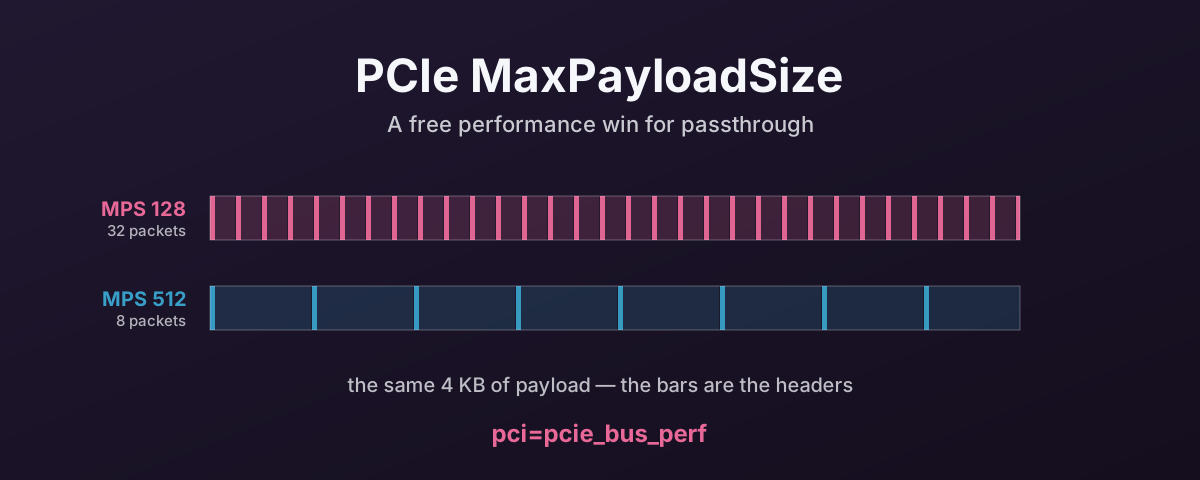
Larger MPS means fewer packets for the same amount of data. A 4KB IO transferred at MPS 128 requires 32 TLPs. The same transfer at MPS 512 requires 8 TLPs.
Each TLP carries protocol overhead — the header, CRC, framing. Fewer TLPs means less protocol overhead per byte transferred. At high throughput, that difference is measurable. Not dramatic. But real. And it is the same overhead, paid on every packet.
MPS also affects how well the PCIe link is used. Smaller payloads mean the link spends more time on headers relative to data. Larger payloads shift the ratio towards useful data.
The impact on latency is smaller than on throughput. A single 4KB read at MPS 128 vs 512 will not show a latency difference worth measuring, because the TLPs are pipelined. But push high IOPS with many transfers in flight and the smaller overhead from larger MPS adds up.
The Problem Under Passthrough
On bare metal, the BIOS sets MPS during POST based on the PCIe topology. A modern server BIOS typically sets MPS to the maximum the topology supports, usually 256 or 512 bytes.
Under QEMU, the virtual Q35 chipset’s root complex has its own MPS capability.
By default, it presents a low MPS.
The Linux kernel’s default MPS policy (pcie_bus_default) sets each device’s MPS to match its parent bridge, which in a virtual topology means the QEMU root complex’s default. Often 128 bytes.
As such, a device that can do 512-byte payloads runs at 128 because the virtual root complex set the ceiling.
How to Fix It — Host Side
Tell the kernel to set MPS to the maximum each device’s parent bus supports:
# Add to GRUB_CMDLINE_LINUX_DEFAULT in /etc/default/grub
pci=pcie_bus_perf
This sets each device’s MPS to the largest value its parent bus allows. It also sets MRRS (Max Read Request Size) accordingly. The kernel source says it makes sure a device’s MPS is no larger than its parent’s. That keeps the chain consistent while getting the best transfer sizes.
After reboot, verify the new MPS:
# Check MPS on a specific device
lspci -vv -s XX:00.0 | grep -i "MaxPayload"
You should see MaxPayload 256 bytes or MaxPayload 512 bytes instead of the default 128.
The Other Kernel Options
The kernel offers four MPS policies, each set via the pci= boot parameter:
pcie_bus_tune_off — don’t touch MPS at all.
Use whatever the BIOS set.
On bare metal with a good BIOS, this is often fine.
Under QEMU, the BIOS is OVMF or SeaBIOS, which may not optimise MPS.
pcie_bus_default — the kernel default.
Sets each device’s MPS to match its upstream bridge.
Conservative and safe, but doesn’t maximise performance.
pcie_bus_safe — sets MPS to the largest value supported by all devices in the system.
Useful for closed systems where you know all devices and nowt will be hotplugged.
Slightly more aggressive than default.
pcie_bus_perf — sets MPS per-device to the largest value the parent bus allows.
Each device gets the best MPS its local topology supports.
This is the right choice for passthrough because it optimises each path independently.
pcie_bus_peer2peer — sets MPS to 128 bytes on everything.
Every device talks at the lowest common size.
Used when devices need to DMA directly to each other (GPU-to-GPU, GPU-to-NIC via RDMA).
Not useful for standard passthrough.
pcie_bus_perf is the right one for passthrough.
How to Fix It — Guest Side
You can set pci=pcie_bus_perf in the guest kernel’s boot configuration as well.
Whether it has any practical effect depends on how QEMU presents the virtual PCIe topology.
The virtual root complex caps what the guest can negotiate.
In testing, the host-side fix is the one that sticks. The host owns the physical device, and its MPS setting sets the actual TLP size on the wire. The guest’s setting only touches the virtual topology inside the VM, and whether that changes real behaviour depends on how QEMU presents the PCIe path for that device.
Set it on the host. Setting it in the guest as well won’t hurt, but don’t rely on it alone.
What MRRS Is
Max Read Request Size (MRRS) is related but separate. MPS limits how much data a device can send in one TLP. MRRS limits how much data a device can request in one read request.
A device with MRRS 4096 can issue a single 4KB read request. The response comes back in multiple TLPs, each up to the MPS in size. Higher MRRS means the device can request more data per transaction, reducing the number of read request TLPs on the bus.
pci=pcie_bus_perf sets both MPS and MRRS to their optimal values.
You don’t need to tune them separately.
Impact vs Other Tuning
The MPS difference between 128 and 512 bytes has a smaller performance impact than NUMA alignment or ASPM. It’s typically a low single-digit percentage improvement on throughput. You won’t see it in latency benchmarks at low queue depths.
But it’s a free optimisation. One kernel parameter, no downside, no compatibility risk. There’s no reason not to set it on any system doing passthrough.
It costs nowt, and you have already paid for the hardware. You may as well have what you bought.
References
- Linux kernel PCI Kconfig — MPS and MRRS tuning options — authoritative source for all four MPS policies
- Linux Plumbers Conference 2017 — MPS vs MRRS (PDF) — Sinan Kaya’s presentation on the kernel’s MPS/MRRS handling